Petrie's Infamous Core #7 |
|||
| Chris Dunn 12/9/99 Part Two I first checked the width between the grooves using the microscope. At this point I was certain that Petrie was totally wrong in his evaluation of the piece. The distance between the grooves, which are scoured into the core along the entire length, was .040 - .080 inch. I was devastated that Petrie even got the distance between the grooves wrong! Any further measurement, I thought, would be just perfunctory. I couldn't support any theory of advanced machining if Petrie's dimensions of .100 inch feedrate cannot be verified! Nevertheless, I continued with my examination.
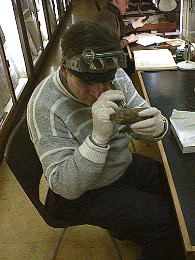
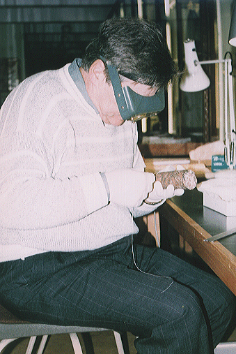
Examining the core with a 50X microscope The crystalline structure of the core under microscope was beyond my ability to evaluate. I could not determine as surely as Petrie did that the groove ran deeper through the quartz than the felspar. I did notice that there were some regions, very few, where the biotite (black mica) appeared to be ripped from the felspar in a way that is similar to other artifacts found in Egypt. However, the groove passed through other areas quite cleanly without any such ripping effect. Though again, I support Brownlee's assertions that a cutting force against the material could rip the crystals from the felspar substrate.
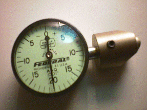
The indicator depth gauge used to I then measured the depth of the groove. To accomplish this I used an indicator depth gauge with a fine point to enable it to reach into a narrow space. The gauge operated so as to allow a zero setting when the gauge was set on a flat surface without any deviations. When the gauge passed over a depression (or groove) in a surface, the spring-loaded indicator point pushed into the groove causing the needle to move on the gauge dial indicating the precise depth.
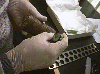
Measuring the depth of the groove on the core The depths of the grooves were .002 and .005 inch. (Actually, because there were clearly discontinuities in the groove at some locations around the core, the actual measurement would be between .000 and .005 inch). Then came the great question. Was the groove a helix or a horizontal ring around the core? I had deferred to Reid and Brownlee's assertions that they were horizontal and I was, at this juncture, painfully assured that it was the correct thing to do. It was Petrie's description of the helical groove that made Core #7 stand apart from modern cores. It was one of the principle characteristics upon which I based my theory of ultrasonic machining. But what I held in my hand seemed to support Reid and Brownlee's objections to this theory, for they said that the core had a similar appearance to any other core one may produce in a quarry. I had rejected my initial plan to fixture the core and rotate it around its central axis to check for a helix. The fixture would have taken time and material to make and, though I had a willing toomaker, Gary Bryant, to manufacture the fixture, I had opted for a cheaper, more primitive, though equally effective, method. The white cotton thread was the perfect choice to inspect for a helical groove. Why not use a thread to check a thread! I carefully placed one end of the thread in a groove while Nick secured it with a piece of Scotch tape. While I peered through my 10 X Optivisor, I rotated the core in my left hand, making sure the thread stayed in the groove with my right.
Nearing the moment of truth with the white cotton thread The groove varied in depth as it circled the core, and at some points there was just a faint scratch that I would probably not have detected with my naked eye. As the other end of the thread came into view, I could see that what Petrie had described about this core was not quite correct. Petrie had described a single helical groove that had a pitch of .100 inch. What I was looking at was not a single helical groove, but two helical grooves. The thread wound around the core following the groove until it lay approximately .110 inch above the start of the thread. Amazingly, though, there was another groove that nestled neatly in between!
Checking the groove at the smaller top end of the core I repeated the test at about 7 different locations on the core with the same results. The grooves were cut clockwise looking down the small end to the large - which would be the top to bottom.
Checking the groove at the mid-section of the core In uniformity, the grooves were as deep at the top of the core as they were at the bottom. They were also as uniform in pitch at the top and bottom, with sections of the groove clearly seen right to the point where the core granite was broken out of the hole.
The white cotton thread showing the helical nature of the groove
Measuring the distance between the spiral groove in the core These are NOT horizontal striations or rings as described in Giza: The Truth, but helical grooves that spiraled down the core like a double-start thread. Petrie's observations are vindicated. The effort to discredit my hypothesis on how this core was produced has fallen short. To replicate this core, therefore, the drilling method should produce the following.
|
|||
| Chris Dunn Ian Lawton Chris Dunn Ian Lawton Chris Dunn Ian Lawton By email to Chris Dunn 12/6/99 Chris Dunn Visit to Petrie Museum Part One - Posted 12/12/1999 Chris Dunn Visit to Petrie Museum Part Two - Posted 12/12/1999 Chris Dunn Visit to Petrie Museum Part Three - Posted 12/12/1999 |
|||
Text and Photographs ©
Copyright 1999 Christopher Dunn With Kind Thanks to the Petrie Museum of Egyptian Archaeology, London. |
|||


